


Quickpass ARE v4
Single Turn Absolute Encoder
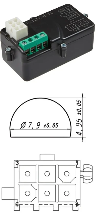
Quickpass ARE v4 is designed to be mounted laterally onto the motor’s gearbox, enabling absolute position detection up to one turn. Thanks to its plug-in connector, installation and removal can be completed quickly and easily, allowing for fast and practical assembly.
Encoder Technical Specifications
| Operating voltage | 7-15VDC |
| Supply Current | 30 mA |
| Operating temperature | -10/+50°C |
| Interface Definition | RS485; Asynchronous Half Duplex Start bit: 1, Data bit: 8, Stop bit: 1, Parity: Even |
| Transfer Speed | 9,600 – 19200 bps |
| Power Up Time | Maximum 50 ms |
| Resolution | 13 bit; 8192 step |
| Absolute Measurement Range | 360° absolute position 0.04395°/step |
| Response Data | 8192 resolution, sent in the range 0..8191 |
| Mechanical Connection | Ø7.9 mm female shaft with half moon slot (4.95 mm)(Fig 1) |
| Protection Class | IP22 |
| Electrical Connections | 1: EMC 2: RS485 A 3: GND 4: RS485 B 5: EMC 6: +VDC |
| Fixing of the encoder | Flat headed screw M4 |
1 Communication Protocol Definition
1.1 Baud Rate Initialization:
Upon powering up, the system starts with a default baud rate of 9600. If it receives five consecutive unidentified requests, it automatically adjusts to the 19200 baud rate, allowing dynamic configuration.
1.2 Response Timing:
There is a minimum required delay of 50 µs between the request and the corresponding response from the encoder.
1.3 Request Protocol:
- Decreasing Value Request: The encoder expects A2 and B0 codes, sent in 2-byte hexadecimal format.
- Increasing Value Request: Similar to decreasing request, but uses code B3 instead of B0.
1.4 Response Protocol:
When a valid request is received, the encoder responds with 3 bytes:
- Byte 1: Always starts with A3
- Byte 2: High byte of position data
- Byte 3: Low byte of position data
The combined position information is in the range of 0 to 8191 (13-bit resolution).
1.5 Error Messages:
The encoder also provides a specific response code for error handling:
- A3 FA FA
2 Standarts
- EN IEC 61000-6-1: Immunity for residential, commercial and light-industrial environments
- EN IEC 61000-6-2: Immunity for industrial environments
- EN IEC 61000-6-3: Emission standard for residential, commercial and light-industrial environments
- EN IEC 61000-6-4: Emission standard for industrial environments

RED ARE
Multi Turn Absolute Encoder
Quickpass RED ARE is designed to be mounted laterally onto the motor’s gearbox, enabling absolute position detection up to 22 turns. Thanks to its plug-in connector, installation and removal can be completed quickly and easily, allowing for fast and practical assembly.
Since it operates without an internal battery, there is no risk of battery depletion or the need for
replacement, ensuring long-term reliability and minimal maintenance.
High‑precision door encoders designed for industrial and comertial door applications. Improve safety, accuracy, and automation performance with reliable encoder technology.
Encoder Technical Specifications
| Operating voltage | 7-15VDC |
| Supply Current | 30 mA |
| Operating temperature | -10/+50°C |
| Interface Definition | RS485; Asynchronous Half Duplex Start bit: 1, Data bit: 8, Stop bit: 1, Parity: Even |
| Transfer Speed | 9,600 – 19200 bps |
| Power Up Time | Maximum 50 ms |
| Resolution | 13 bit; 8192 step |
| Absolute Measurement Range | 7920° absolute position 0.9668°/step |
| Response Data | 8192 resolution, sent in the range 0..8191 |
| Mechanical Connection | Ø25 mm male shaft with key slot (6 mm)(Fig 1) |
| Protection Class | IP4f2 |
| Electrical Connections | 1: RS485 A 2: +VDC 3: GND 5: RS485 B |
| Fixing of the encoder | Flat headed screw M4 |

1 Communication Protocol Definition
1.1 Baud Rate Initialization:
Upon powering up, the system starts with a default baud rate of 9600. If it receives five consecutive unidentified requests, it automatically adjusts to the 19200 baud rate, allowing dynamic configuration.
1.2 Response Timing:
There is a minimum required delay of 50 µs between the request and the corresponding response from the encoder.
1.3 Request Protocol:
- Decreasing Value Request: The encoder expects A2 and B0 codes, sent in 2-byte hexadecimal format.
- Increasing Value Request: Similar to decreasing request, but uses code B3 instead of B0.
1.4 Response Protocol:
When a valid request is received, the encoder responds with 3 bytes:
- Byte 1: Always starts with A3
- Byte 2: High byte of position data
- Byte 3: Low byte of position data
The combined position information is in the range of 0 to 8191 (13-bit resolution).
1.5 Error Messages:
The encoder also provides a specific response code for error handling:
- A3 FA FA
2 Standarts
- EN IEC 61000-6-1: Immunity for residential, commercial and light-industrial environments
- EN IEC 61000-6-2: Immunity for industrial environments
- EN IEC 61000-6-3: Emission standard for residential, commercial and light-industrial environments
- EN IEC 61000-6-4: Emission standard for industrial environments